Overview
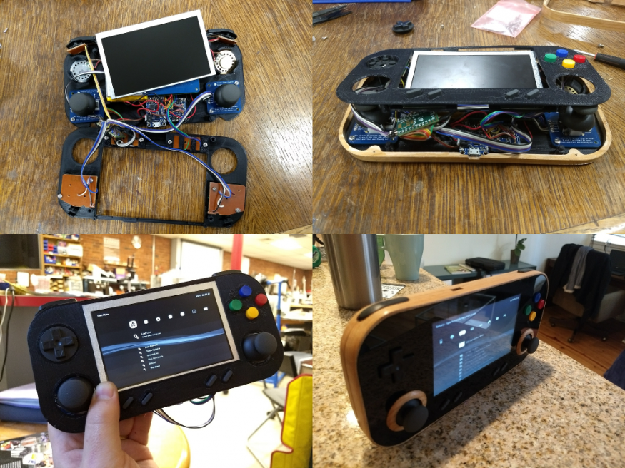
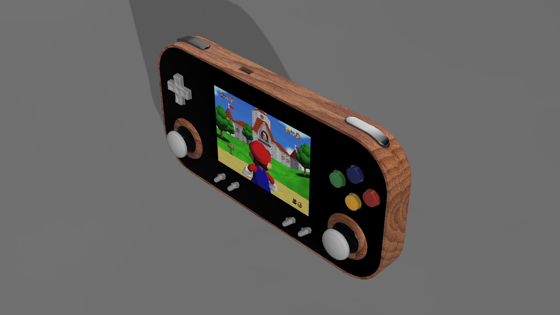
The idea was to use a Raspberry Pi 3, tear down a SNES controller for getting some parts like the buttons and the PCBs, use some wood and acrylic to make it look nice and add some 3d-printed plastic to hold it together. On the Raspberry Pi 3, I installed a customized version of a linux distribution called Lakka, it emulates a lot of old consoles, from the Atari 2600 and NES up to the Playstation 1 and the Nintendo 64. A Teensy 2.0 board was used for implementing the controller logic and adding two extra analog joysticks.
Material
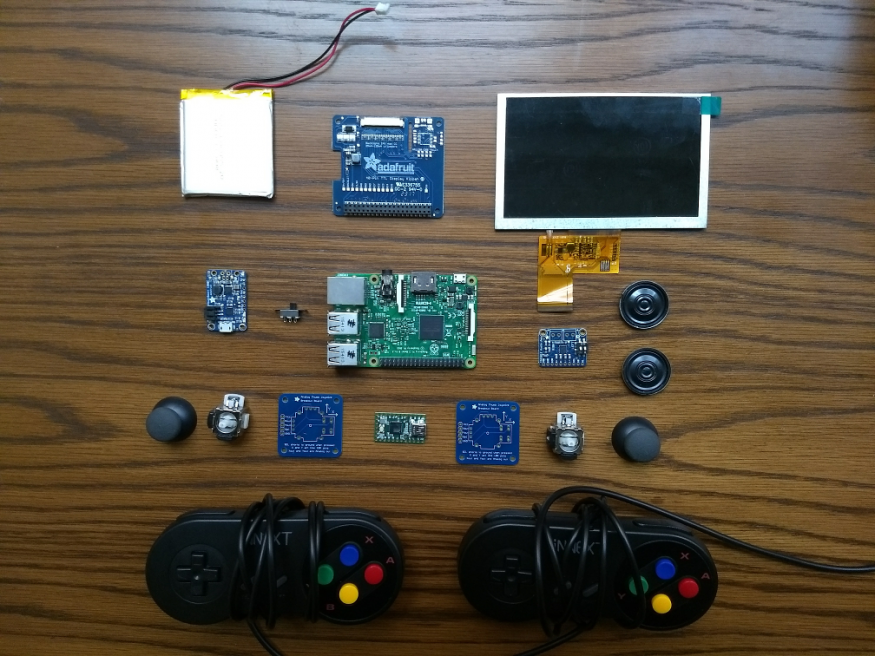
- Raspberry Pi 3
- Micro SD card with at least 8GB of memory
- Stereo 2.1W Class D Audio Amplifier - TPA2012
- PowerBoost 1000 Charger - Rechargeable 5V Lipo USB Boost @ 1A - 1000C
- Lithium Ion Polymer Battery - 3.7v 2500mAh
- Adafruit DPI TFT Kippah for Raspberry Pi
- 5.0" 40-pin 800x80 TFT Display without Touchscreen
- Slide power switch
- Mini USB male socket
- Ribbon cable
- Pack SNES Controllers Kiwi Tata
- Adafruit analog joystick with select button (x2)
- Teensy 2.0 board
- M2.5 Tapered Shank Heat-Set Insert
- Pan Head Machine Screw: 18-8 Stainless Steel, Phillips, M2.5
- 1/16" transparent acrylic sheet (available at the MakeHaven store)
- Some wood(this place is great), I used cherry
Tools and supplies
- 3d printer + filament
- Laser cutter
- CNC machine
- Wood workshop tools including a planer, and a drill press
- Soldering iron + solder
- Small phillips screwdriver
- Wood finishing product
- Paint bomb
- Super glue gel
3d design
I used the free version of Fusion360 for designing all the parts. The archive of the project can be downloaded here.
3d printed parts
Four parts need to be printed, the bottom assembly, the top assembly and two button supports for the select/start and volume-/volume+ buttons. Below are the corresponding stl files:
| bottom_assembly.stl | 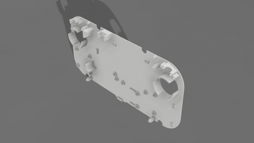 |
| top_assembly.stl | 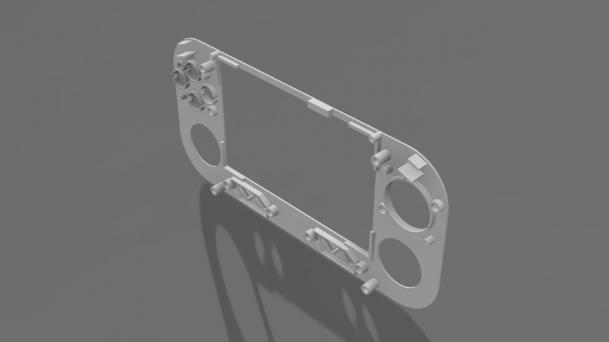 |
| button_support.stl (x2) | 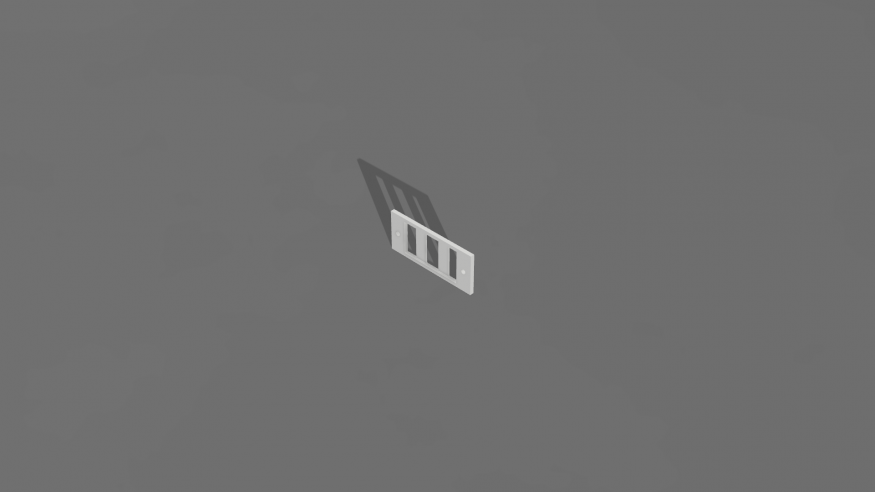 |
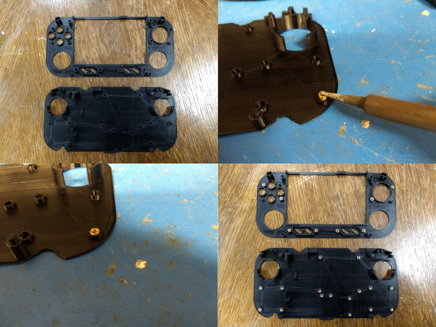
I used a raft for printing the bottom assembly as it might otherwise be difficult for the first layer to stick correctly on the bed because of all the small holes designed for the heat set inserts.
Once the parts printed, I inserted the inserts as shown on the picture below. You simply have to put the inserts in top of the holes, take a soldering iron heated to 230ºC and gently press with the iron tip on top of the inserts.
Acrylic top
Laser cutting
For laser cutting the acrylic top, I exported a dxf file from one of the sketches in my Fusion360 project(see Acrylic top->Sketches->Laser cut export in the project). I cut with the following settings:
- Speed: 30%
- Power: 90%
- Frequency: 1000 ppi
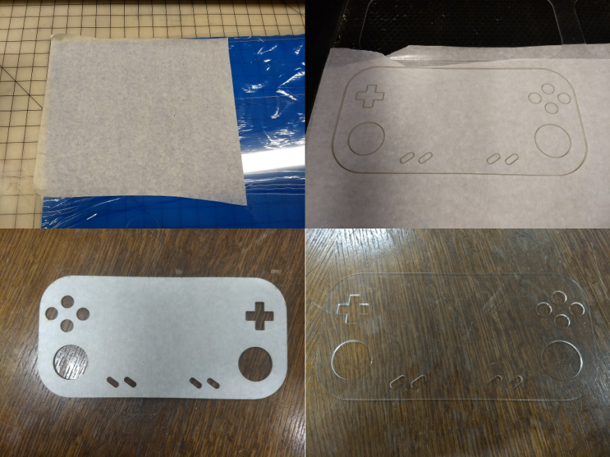
Many passes were necessary for the laser to cut through. I apply transfer tape on both sides of the acrylic sheet in order to avoid burn marks.
You can see the final result on the pictures below:
Painting
Only the screen needs to be seen, that's why I painted the whole bottom of the acrylic top except for the rectangle where the screen will appear. To do that, I once again exported a dxf file from my Fusion360 project (see Marquee->Sketches->Export), printed it on paper, aligned the acrylic on top of it, used some tape to cover the parts I didn't want to be painted and sprayed paint all over it:
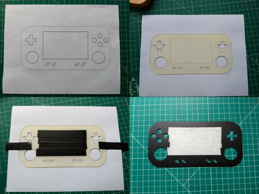
Obviously the picture of the bottom right-hand corner does not correspond to the final result. After this step, I applied some tape vertically and sprayed paint one more time to get the final result. For each iteration, two to three layers of paint were needed for the result to be homogeneous.
Controller
Tear-down
I tried to recuperate most of the parts of the controllers which means the buttons, the silicone rubber pads, the PCB and even the screws that I kept for holding the bottom and top parts of the wood case.
I opened the controller, unsoldered all that needed to be unsoldered and cut the main PCB in three pieces as shown below:
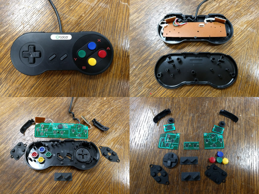
I tore down the second controller to get an other select/start PCB part and buttons for the volume up/down controls.
Circuit
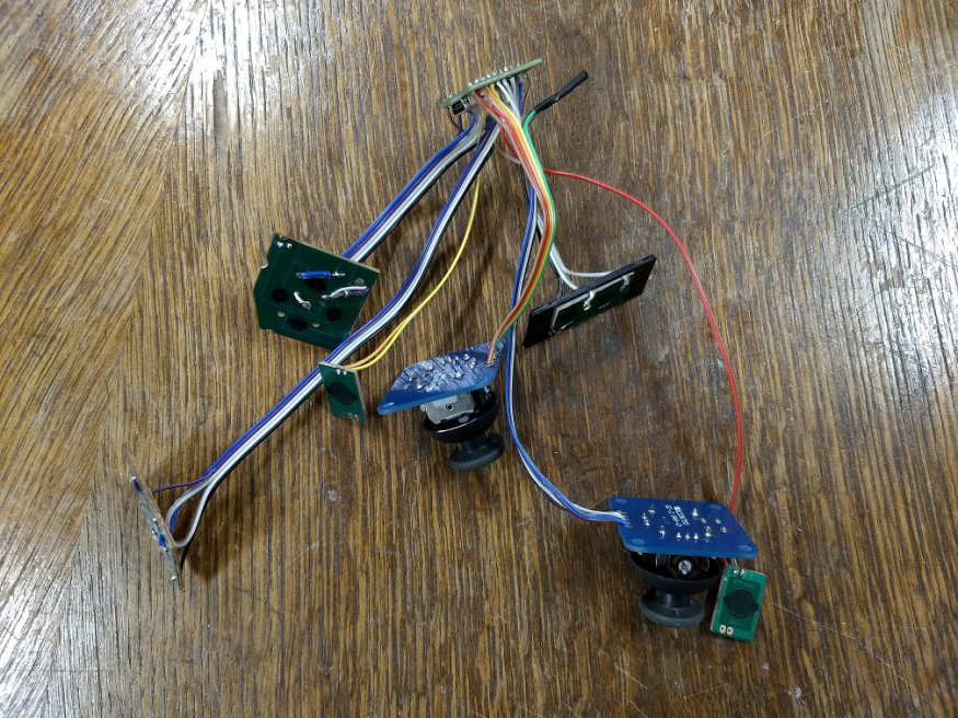
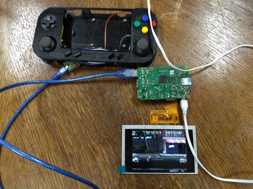
I soldered all the parts together accordingly to the schema below:
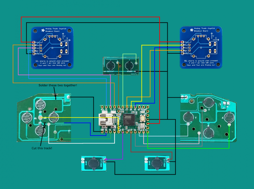
At the end I got something that looks like this:
Teensy programmation
As stated on their website, the Teensy is a complete USB-based microcontroller development system, in a very small footprint, capable of implementing many types of projects. I used the 2.0 version as it suited my needs and is the cheapest one. In this project, it reads the different buttons states, the analog values of the two joysticks and acts as a USB controller for the Raspberry Pi. To program it, I used Teensyduino which is a software add-on that allows to program the Teensy using the Arduino IDE. The code is straightforward as Teensyduino already comes with a USB Joystick library. The only problem that I had is that the device was enumerated as three different devices: a keyboard, a mouse and a controller which got the Raspberry Pi confused. That's why I had to modify the library for it to be enumerated only as a controller.
The code of the library, the arduino sketch as well as the instructions to compile and load it are available here on my github profile.
Raspberry Pi 3, battery and audio
System
I chose to install Lakka on the Raspberry Pi for several reasons:
- The playstation 3-like interface is really nice
- Some features like Netplay and Shaders are easily accessible via the UI
- Because it is based on LibreELEC, it boots really fast
However I needed to do some changes:
- As I used the Adafruit's kippah for the display, the linux device tree had to be modified in order to redirect the display to the pins used by the kippah. The Raspberry Pi bootloader configuration file (/boot/config.txt) also had to be modified for the display to be properly configured. Some samples of both the device tree source and config.txt are available on the Adafruit's github: here.
- I use two Raspberry Pi's GPIO pins for controlling the volume (up and down), that's why I added a small daemon written in C that reads the GPIOs via the WiringPi library and adjusts the volume using the ALSA library. The dameon's code can be found here on my github.
- I added a preinstalled "auto" configuration file for the Teensy controller: here.
In order to have a system image that suited my needs I forked the libretro/Lakka-LibreELEC project, added my modifications and built a new image following these instructions.
The code is available here on my github profile. I also uploaded a ready-to-use image here.
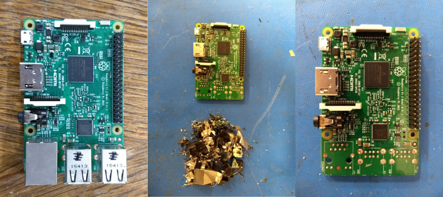
Diet Raspberry Pi
I wanted the console to be as thin as possible and the best way to achieve that was to put the Raspberry Pi on a diet. I simply savaged the connectors with some nippers, taking care of not removing the components nearby.
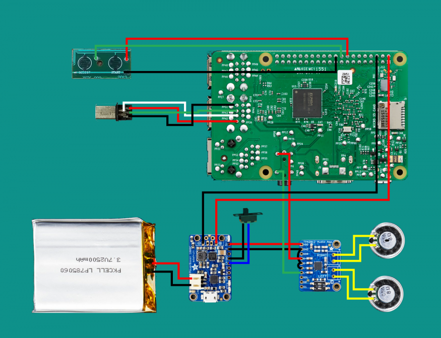
Circuit
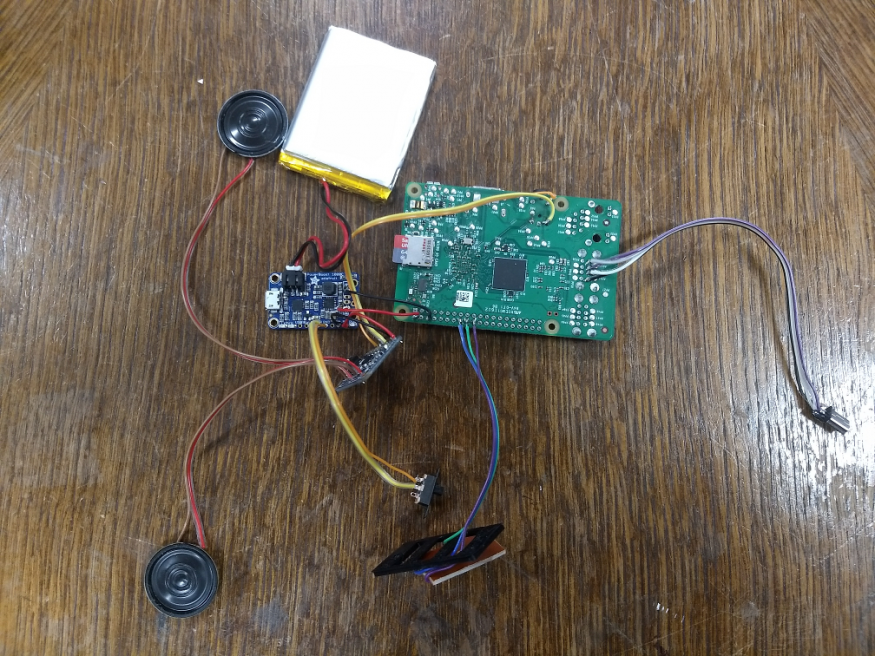
I finally soldered the Raspberry Pi and all the remaining components according to the schema below:
At the end, I got someting that looks like this:
Wood case
Milling
I used the Shapeoko CNC machine with 1/4" and 1/8" flat end bits for milling the wood case and the two joystick masks. The software that controls the Shapeoko is called easel. With easel you can either use its integrated editor (2d only), import an svg file or import gcode directly to generate the toolpath. As I needed to mill in 3d, I generated the toolpaths with the Fusion 360's CAM module and used the easel post processor (see here how to install it) to generate easel-compatible gcode.
For milling both sides of each piece I applied the method described in this video.
Before starting to mill, it is a good idea to pass the stock in a planer for it to be as even as possible. Otherwise you can really have bad surprises, principally when you flip the stock and start milling on the other side.
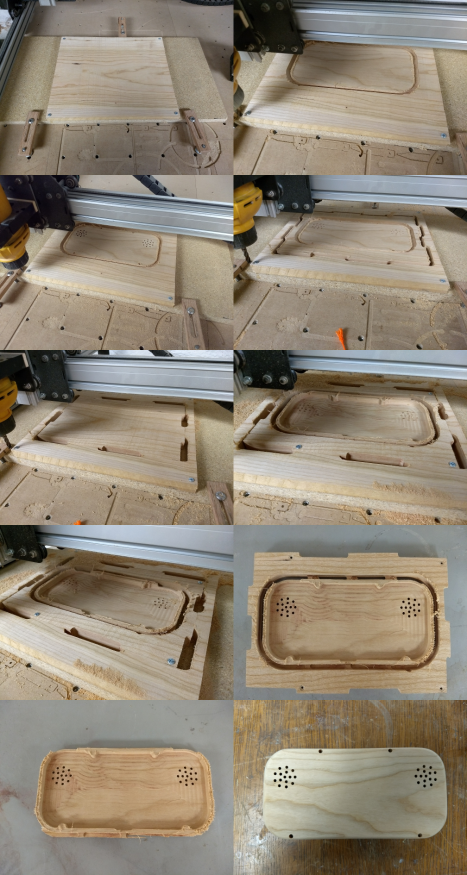
Case bottom
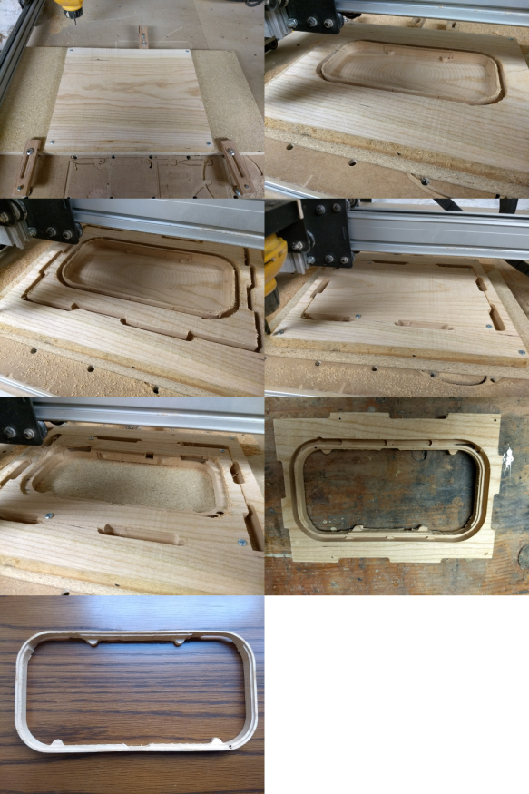
Case top
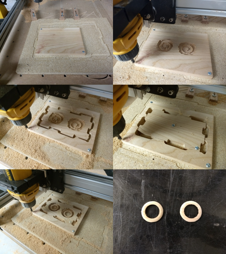
Joystick masks
Finishing
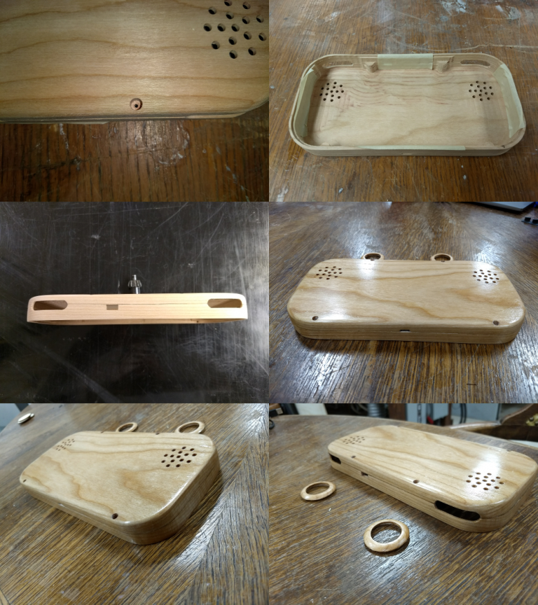
I taped the top and the bottom of the case together and drilled four small holes (~1/16" diameter). I screwed them together with the screws I recuperated from the controller.
Finally I sanded them with finer and finer grits and applied several coats of shellac.
Final assembly
To assemble everything, I glued the acrylic top to the top of the wood case, put the buttons in their respective places, screwed the different PCBs to the plastic assembly, connected the screen to the display, the controller and the kippah to the Raspberry Pi, the battery to the power boost and inserted all that into the wood case. Finally I closed it and screwed the top and the bottom together.